NEXOFEED / products
Step Feeder Hopper
In modern industrial production, the storage and transportation of materials are key to ensuring smooth production processes and improving production efficiency. With the continuous advancement of industrial automation, various efficient material handling equipment has emerged, w…
Evaluate with my part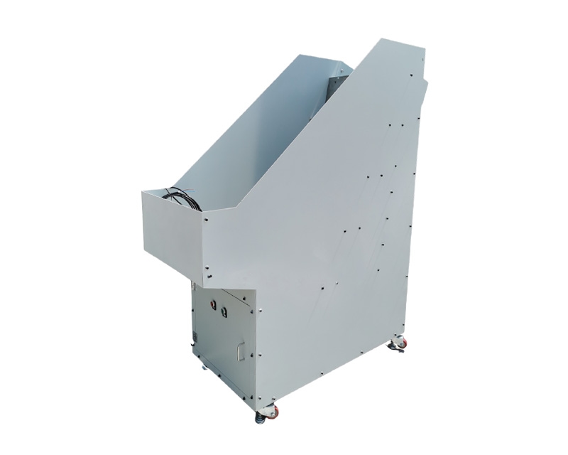
Overview
In modern industrial production, the storage and transportation of materials are key to ensuring smooth production processes and improving production efficiency. With the continuous advancement of industrial automation, various efficient material handling equipment has emerged, with the pusher type silo being one of the most representative examples. With its unique structural design and working principle, the pusher type silo enables orderly storage and precise conveying of materials, and is widely used in various industrial fields. This article will provide a detailed explanation of the pusher type silo from its structural components, working principles, application scenarios, advantages, common issues and solutions, and maintenance, fully unveiling the mystery of the pusher type silo and assisting in its rational application and optimized management in industrial production.
The silo body is the main part of the pusher type material storage in the material bin, with its shape and size determined by the actual application scenario and material storage requirements. Common silo shapes include rectangular and cylindrical shapes. Rectangular warehouses offer flexible space utilization, better adapting to different factory layouts, and are suitable for situations with special requirements for storage capacity and space planning; Cylindrical silos perform excellently in force uniformity and sealing, commonly used to store powder, granular, and other materials that require high sealing. The silo body is usually made of high-strength steel or stainless steel plates to ensure sufficient strength and stability, able to withstand the weight of the material and the forces generated by the pushing plate. At the same time, to prevent materials from sticking to or corroding the silo body, special treatments are applied inside some chambers, such as spraying anti-corrosion coatings and installing wear-resistant liners.
The pushing mechanism is the core actuating component of the pusher type silo and directly determines the efficiency and stability of material conveying. The push plate mechanism mainly consists of the push plate, transmission device, and drive unit. The push plate is generally made of high-strength, wear-resistant materials, with its shape and size matching the internal space of the silo body, ensuring a tight fit against the silo wall during material delivery and reducing material residue. The transmission device is responsible for delivering the power from the drive device to the push plate. Common transmission methods include chain drive, belt drive, and screw drive. Chain drives feature high transmission efficiency and strong load capacity, making them suitable for transporting heavier materials; Belt drives, on the other hand, offer smooth operation and low noise, and are often used in scenarios with high working environment requirements; Screw drives enable precise linear motion control, suitable for applications requiring strict material conveying accuracy. The drive device provides power for the movement of the push plate, with common drive methods including electric drive, hydraulic drive, and pneumatic drive. Electric drives feature convenient control and high precision, allowing adjustment of different speeds and thrusts of the push plate through a combination of a motor and reducer; Hydraulic drive can provide significant thrust, suitable for pushing heavy and high-resistance materials; Pneumatic drives offer fast response and low cost, and are often used in situations where high speed is required and thrust is relatively low.
The guiding device ensures that the push plate moves smoothly along the predetermined direction during movement, preventing the plate from shifting or jamming, thereby guaranteeing the accuracy and reliability of material conveying. Common guide devices include guide rails and guide rods. Guide rails are usually installed on both sides or bottom of the silo body. The push plate works with the guide rail via sliders, enabling linear movement under the constraints of the rail. The precision and rigidity of the guide rails have a significant impact on the movement accuracy and stability of the push plate. High-precision guide rails can effectively reduce friction and shaking during the push plate's movement, improving material conveying accuracy. Guide rods are generally installed vertically inside the chamber, with the push plate cooperating with the guide rod through a guide sleeve, which provides vertical support and guidance for the push plate. In some large pusher type silos, a combination of guide rails and guide rods may be used to further enhance the stability and reliability of the pusher movement.
The control system is the key part for achieving automated operation of the pushing machine type silo. It can precisely control and monitor the operating status of the pushing mechanism according to production process requirements. The control system mainly includes sensors, controllers, and actuators. Sensors are used to monitor the status of materials inside the silo in real time, such as material height, push plate position, and operating speed. Common sensors include material level sensors, displacement sensors, and speed sensors. Level sensors can use various principles such as ultrasonic, radar, and weight-type sensors to detect the storage height of materials inside the silo. When the material reaches the preset upper or lower limit, it promptly sends a signal to the controller; The displacement sensor can accurately measure the position of the push plate, ensuring it moves according to the predetermined stroke; The speed sensor monitors the running speed of the push plate, allowing the controller to adjust the speed as needed. The controller is the core of the entire control system and typically uses devices such as programmable logic controllers (PLCs) or industrial computers. The controller receives signals from the sensor, processes them logically, and sends control commands to the actuator, enabling operations such as starting, stopping, adjusting speed, and controlling direction on the push plate mechanism. The actuator drives the push plate mechanism according to controller instructions, such as controlling motor speed and direction, adjusting hydraulic system pressure and flow, and controlling the opening and closing of pneumatic components.
Features
- Step lifting with less continuous vibration
- Part-configured hopper and discharge
- Low- and full-level sensing available
Benefits
- Reduces repetitive manual handling
- Presents parts consistently to the next process
- Supports integration with automated equipment
PARTS
Supported parts
- Long, heavy or regularly shaped parts
- Shafts, bolts and cylindrical components
- Parts sensitive to noise or continuous vibration
Want to evaluate this solution with your part?
Send photos, dimensions, orientation and rate. We will respond with the next technical questions.
Request a quote