TECHNICAL GUIDE
A connector bowl feeder is often discussed as a machine that sorts parts. For the assembly engineer, however, the decisive question is what arrives at the receiving point: which connector, in which attitude, at what moment, with what access for the next tool. A productive layout begins with that handoff and works backward toward the bowl.
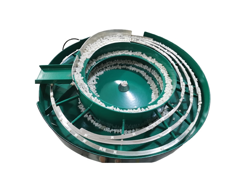
The NexoFeed YH-753 Connector Vibratory Bowl Feeder is cataloged with part-specific orientation tooling and adjustable vibration and flow control. Its configuration and rate require sample evaluation. The layout options discussed here are questions for that evaluation, not a statement that every arrangement is included with this catalog reference.
View the application workflow diagram (conceptual illustration)
Start with the receiving operation
Identify the operation immediately after feeding. A connector may enter a locating nest, wait for robotic pickup or move toward an inspection position. Each operation imposes different limits on access, support and timing. Show the receiving equipment in its working position rather than sending only a photograph of an empty machine frame.
Mark the required connector face, leading edge and rotational attitude. Include the gripper approach and any surfaces that must remain available to another tool. An attractive straight-line layout is not useful if its discharge track occupies the same space as the receiving mechanism.
Describe demand as a sequence
A receiving station does not necessarily consume connectors at a constant interval. It may request one part, wait through an operation, and then pause while another component is loaded. Supply the normal sequence and describe what happens during inspections, tool changes and short downstream interruptions.
Distinguish the required production output from a momentary demonstration of movement along a track. The application review should establish whether correctly presented parts remain available at the required point throughout the agreed sequence. A speed number without this context can hide an unsuitable transfer arrangement.
Evaluate a single discharge first
A single discharge can provide a clear responsibility boundary: one queue supplies one receiving position. This can simplify discussions about part availability and pickup confirmation. It does not make the arrangement automatically suitable; access, changeover and required capacity still need review against representative samples.
Ask where separation occurs and how the last connector is held before release. A line of correctly oriented parts is not the same as a single connector ready for pickup. Document which device performs that final separation and which team supplies its controls and mechanical interface.
Treat additional lanes as a separate design question
When more than one station needs connectors, do not assume that adding another track simply doubles useful output. The proposal must explain how each lane is supplied, what happens when one station pauses and whether a shortage in one path can affect another.
Compare a shared feeding arrangement with separate dedicated arrangements at the application level. Include space, service access, component mix and the consequences of a stoppage. These tradeoffs require an engineered proposal; this guide does not establish a supported lane count for the YH-753.
Consider the queue, not just the exit
Ask how connectors behave while waiting. A projecting latch may face a different contact condition in a stationary queue than during free movement. Mark acceptable support surfaces and any features that must not carry accumulated contact force. Use the actual assembled state, including installed elements where applicable.
The queue should also remain accessible for approved inspection and recovery. A compact layout that hides the final transfer can make diagnosis difficult. Review visibility from the normal operating position without expecting an operator to reach into guarded equipment to determine whether a connector is present.
Compare orientation with verification
RNA's feeder FAQ describes bowl feeding in terms of sorting and orienting components from bulk. That is a useful boundary for specifications: mechanical presentation is not automatically an identity check, an electrical test or a complete inspection of connector condition.
If a project needs confirmation of a particular cavity arrangement, color or populated contact pattern, list that as a distinct requirement. Ask how it will be verified and what happens to an unacceptable part. Do not infer inspection capability merely because a sensor is shown near the discharge.
Plan service and changeover access
Review the space needed to identify and replace approved tooling. A layout drawing should show more than the equipment footprint; it should allow the delivered maintenance and changeover procedure to be performed safely. Consider how operators identify the correct change parts and where removed parts are stored.
For related connector variants, record which elements remain common and which require a change. Avoid describing the system as universally flexible before evaluation. A small change in housing geometry can alter orientation or support even when the overall connector dimensions appear similar.
Make the sample trial answer layout questions
The trial should address the proposed receiving arrangement, not just show parts traveling around the bowl. Use representative variants and define acceptable presentation at each required discharge. Include the agreed pause and restart conditions so waiting behavior is visible during the review.
Keep a record of interruptions and their locations. Distinguish a loss of orientation before discharge from a receiving nest that was not ready. This separation helps determine whether the proposed change belongs in feeder tooling, the transfer mechanism or the receiving station sequence.
Assemble a layout decision sheet
Before selecting an arrangement, bring together:
- A component drawing and marked delivery attitude.
- The actual component state and protected features.
- Receiving-tool approach, clearance and support requirements.
- Demand sequence for each receiving position.
- Proposed separation and availability-confirmation responsibilities.
- Changeover boundaries and service access.
- Observable acceptance conditions for the complete handoff.
Use the sheet to compare proposals on the same basis. It prevents one option being judged on bowl movement while another is judged on completed transfer. Keep unresolved points visible so they become evaluation tasks rather than assumptions hidden in the purchase description.
Questions to resolve before quotation
Does a second lane guarantee twice the production?
No. Useful output depends on the evaluated arrangement and the receiving process. Lane balance, waiting behavior and transfer requirements must be considered separately.
Can a feeder layout replace connector testing?
No. Specify electrical and product-quality tests independently. Correct orientation alone does not demonstrate conformity of the connector assembly.
What information should accompany an inquiry?
Request a YH-753 application review with a receiving-station drawing, representative samples and the proposed production sequence. Ask for a discharge arrangement justified by those requirements, with capacity and configuration confirmed through evaluation.