GUÍA TÉCNICA
“Electronic plug” can describe a molded body, a component containing contacts or a more complete assembly. That difference matters when specifying automatic feeding. A track that supports a bare housing may contact a sensitive feature on a populated assembly. A feeding proposal should therefore begin with the exact component state, not a broad product category.
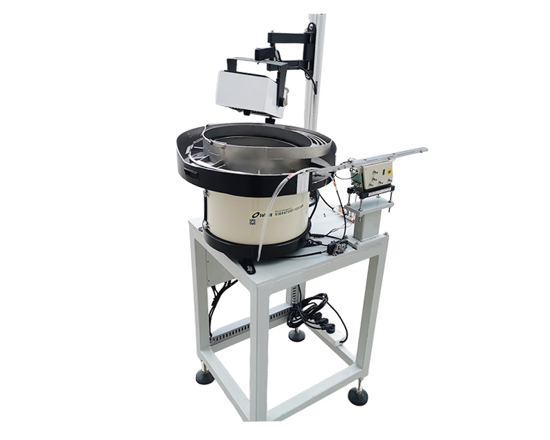
The NexoFeed YH-764 Electronic Plug Vibratory Bowl Feeder is listed with part-specific orientation tooling and adjustable flow control. The catalog specifies that configuration and rate are confirmed through sample evaluation. This guide explains how to prepare that evaluation, with particular attention to the mating face, keying features and receiving operation.
View the application workflow diagram (conceptual illustration)
Identify what is actually loaded
Provide the component drawing and describe which elements are present when the plug enters the feeder. State whether contacts, seals, clips or other features are already installed. If wires or another attached element are present, show the actual assembly and its handling restrictions rather than assuming the same bulk-feeding concept applies.
Identify the supplier, revision and approved variants. Closely related plugs may share an outline while differing in keying or a small locating feature. The engineering team needs those distinctions to decide what the tooling can use for orientation and what requires a separate identification or inspection step.
Define the mating face without ambiguity
Mark the mating face on the drawing and show the required pose at the receiving station. Also identify the leading end and any rotational requirement. “Contacts forward” can be ambiguous if the next operation receives the part from a different direction or if contacts are not present at that stage.
Use an annotated image showing the actual pickup or placement viewpoint. Include the features used by the receiving nest or gripper. This establishes a common reference for the feeder supplier and the assembly-machine integrator and avoids approving a presentation that is correct only from one viewing angle.
Distinguish locating features from protected features
A key, latch or projecting contact may help identify orientation visually, but that does not make it a suitable surface for mechanical guidance. Mark where the proposed tooling may support the plug and where contact or loading should be avoided. Base those limits on the component requirements.
Ask how the selected attitude is preserved along the entire route. A plug can leave a bowl in the correct direction and rotate during a transition. Review the transfer and receiving nest together, including whether the body remains supported without pressing on a feature that must remain undamaged.
Separate feeding from electrical verification
A bowl-feeding system does not automatically verify contact retention, electrical continuity or correct internal assembly. If those checks are necessary, describe them as separate inspection requirements. Agree where they occur and how a failed part is handled.
Likewise, a successful orientation trial does not prove that the finished plug meets its application requirements. Feeding acceptance should establish the agreed mechanical presentation and part condition. Product qualification and electrical testing remain with the relevant quality and engineering processes.
Evaluate incoming condition and normal variation
Supply samples as they will arrive at the production cell. Describe permitted residue, protective packaging and any storage conditions relevant to the component. Do not prepare unusually clean or hand-selected samples without telling the evaluation team how they differ from normal production.
Where material, color or supplier varies, label the sample groups. These differences may influence the proposed handling or detection arrangement. A sensing method that works with one appearance should not be assumed to behave identically with all approved versions. Include the required variations in the evaluation plan.
Discuss the production mix
A stable plug family may justify dedicated part-specific tooling. A broader mix may call for change parts, separate feed paths or another presentation method. Compare the complete changeover task, including line clearance and receiving-tool replacement, rather than considering only controller settings.
If two variants can physically pass through the same track, define how the correct variant is ensured. Incoming identification may be sufficient for one process, while another may require automatic verification. The important point is to agree the responsibility explicitly instead of expecting the orientation mechanism to recognize every part number.
Define the handoff sequence
Describe how the receiving machine requests a plug and confirms that the pickup position is available. Identify whether a controlled queue is needed and how the feeder should respond to a downstream pause. Review the condition of plugs waiting in that queue, not just those moving through it.
The release arrangement should be matched to the actual operation. A press fixture, gripper or inspection station may require a different approach to support and access. Include the receiving-tool envelope and maintenance access in the layout so the final handoff does not depend on an awkward or unsupported transition.
Write acceptance criteria that can be observed
Specify correct face direction, rotational condition where needed, single-part presentation and acceptable component condition. Identify the inspection method for protected features. Do not rely on statements such as “feeds smoothly” when different reviewers could interpret them differently.
Test representative components through the complete route. Include normal replenishment and relevant stops or restarts. Record any intervention and the associated part condition. If a part is rejected, determine whether the rejection is an intended response to an unacceptable condition or evidence that normal production variation needs further evaluation.
Prepare the application review package
Before requesting a proposal, assemble:
- The exact plug part number, revision and assembly state.
- A drawing marking the mating face and required pickup pose.
- Protected contacts, latches and other sensitive features.
- Representative production samples and approved variants.
- Receiving-tool details, available space and discharge height.
- Production demand, pause behavior and changeover expectations.
- Required identification, inspection and acceptance responsibilities.
A complete package reduces the chance of designing an apparently suitable feeder around the wrong component state. It also gives the receiving-machine team an opportunity to identify constraints before the feeding arrangement is finalized.
Common questions
Can one feeder handle a bare housing and a populated plug?
Not automatically. The added components may change contact restrictions, balance and the required support. Evaluate each actual state.
Does mechanical keying eliminate inspection?
No. Keying can help establish presentation, but it does not prove identity or internal condition unless a specific verification function is included and validated.
What should I do next?
Request an electronic plug feeding review with reference YH-764. Include the mating-face drawing and actual assembly samples so the proposed handling route can be assessed against the real receiving operation.