GUÍA TÉCNICA
Two pins can share the same nominal length and diameter yet require different feeding arrangements. A head, unequal end treatment, shoulder or contact feature can determine how a pin should be oriented and supported. Selecting a feeder from dimensions alone overlooks the information that the receiving operation actually needs.
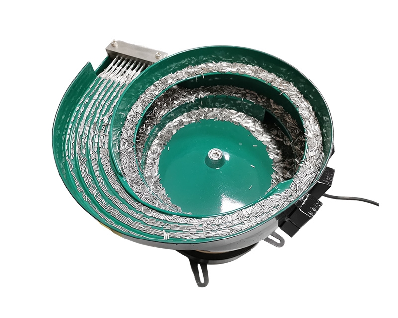
The NexoFeed YH-745 Pin Vibratory Bowl Feeder is listed for part-specific orientation with adjustable vibration and flow control. Its configuration and rate require evaluation of the actual part and process. This guide focuses on the questions that make that evaluation useful, rather than assuming a universal setup for every item described as a pin.
View the application workflow diagram (conceptual illustration)
Identify the exact component type
Provide the pin drawing, part number and revision. State whether the item is an electrical contact, a locating component or another pin-shaped part. Do not use a general photograph of a similar component when the actual item has different ends or surface requirements.
Identify the state in which the part enters the feeding system. A bare pin, a coated pin and a pin with an attached element should not be treated as interchangeable samples. Explain the incoming packaging and any approved restrictions on contact, contamination or handling before a feeding concept is selected.
Decide whether the ends are interchangeable
Review the component drawing with the receiving-process owner. If either end is acceptable, record that explicitly. If a particular end must lead, show the distinguishing feature and provide an annotated view of the required delivered pose. An end difference that is obvious under magnification may not be suitable for every orientation method.
Avoid assuming that apparent symmetry means process symmetry. The receiving operation may depend on an end treatment or feature not obvious in a catalog photograph. The feeder evaluation must use the actual requirement, not an operator's informal description of which end looks similar.
Define the supported and protected surfaces
Mark the surfaces that may contact tooling and those that require protection. For an electrical contact pin, the accepted condition of relevant surfaces should come from the component requirements. For another pin type, a locating diameter or end feature may be the critical area.
Do not infer surface protection from the feeder's general appearance. Ask how support is maintained through the proposed route, including transitions and waiting positions. Any proposed contact material or special handling feature needs to be confirmed in the application scope rather than assumed to be standard equipment.
Describe the final pose, not only track direction
State whether the receiving point requires a horizontal, vertical or otherwise defined presentation. Mark the axis, leading end and available access. Include the location of the receiving datum and the tool envelope so the feeder supplier can assess the whole transfer.
The final pose should be defined at the responsibility boundary. A pin aligned along an upstream track may still require a separate transfer before it can be installed or inspected. Identify who supplies that function and how it preserves the required orientation.
Separate feeding from insertion
SPIROL's pin installation overview illustrates that feeding and installation can be coordinated within an assembly system. Its equipment details are not specifications for YH-745. The useful planning distinction is that presenting a pin and performing an insertion are separate functions that require a defined interface.
If the next operation installs the pin, describe that operation to the integrator and identify its acceptance requirements independently. A feeder trial does not establish insertion force, finished-joint quality or the suitability of the component for its eventual application.
Evaluate production variation deliberately
Supply representative samples and identify approved differences between lots or variants. Include relevant drawing tolerances in the review rather than asking the supplier to infer them from a small sample. Label groups so any observed behavior can be associated with a particular component condition.
If a pin family contains closely related lengths or end forms, list them separately. Ask which differences can share an evaluated arrangement and which require tooling or setup changes. Do not assume that a broad size range in an inquiry guarantees automatic discrimination between all components inside that range.
Review separation at the receiving point
Determine what establishes that one pin, rather than an uncertain quantity, is available for the next operation. A supply track containing pins does not itself prove single-part presentation. Ask how the proposed release arrangement supports the pin while the receiving tool approaches.
Review what happens when the receiver pauses. The agreed arrangement should preserve a known state and acceptable part condition while waiting. If a special detection function is needed, define it explicitly and agree how its intended performance will be evaluated.
Make the trial reflect the actual handoff
Observe representative pins through the complete proposed route. Include the relevant receiver demand sequence and the normal operating conditions agreed for evaluation. Record interruptions at their first observable location instead of reporting every event as a general failure to feed.
Examine delivered samples using the accepted inspection method. Verify both presentation and condition. If a trial succeeds only with hand-selected material or an unrepresentative receiving arrangement, record that limitation so it does not become an unsupported production claim.
Prepare a pin-feeding inquiry
An effective inquiry includes:
- The exact pin drawing, revision and application description.
- Required leading end and final delivery pose.
- Protected surfaces and acceptable incoming condition.
- Representative samples and identified variants.
- Receiving-tool access, datum and available space.
- Required production sequence and pause behavior.
- Separate responsibilities for feeding, inspection and installation.
Keep the evaluation questions attached to the sample groups. This makes the review easier to reproduce and helps connect a proposed tooling arrangement to the conditions it was actually intended to handle.
Common questions
Can the same feeder handle any pin of similar size?
No such compatibility is established by dimensions alone. End geometry, surface condition and the receiving operation require application-specific review.
Does a part-present signal prove correct orientation?
Not necessarily. Its meaning depends on the detection function supplied and validated for the project. State orientation verification as a separate requirement where needed.
What should I do before ordering?
Request a YH-745 sample evaluation with the required end and receiving pose clearly marked. Ask for configuration and capacity to be confirmed against the actual pin and handoff, not against a generic pin-feeding demonstration.