GUÍA TÉCNICA
A printer roller gear feeder should be selected around the condition of the gear when it reaches assembly, not simply the movement visible inside the bowl. A gear that arrives quickly but with its hub facing the wrong way can still stop a shaft-loading station. Likewise, a correctly oriented gear is not acceptable if its teeth have been marked during handling. These two requirements—presentation and part condition—belong in the same specification.
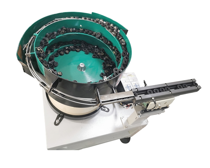
NexoFeed lists the YH-748 Printer Roller Gear Vibratory Bowl Feeder for this application. Its published specification identifies part-specific tooling, adjustable vibration and flow control, with final configuration and rate confirmed through sample evaluation. The following guide explains what to establish before requesting that evaluation. It is a selection framework, not a guaranteed operating specification for every gear.
View the application workflow diagram (conceptual illustration)
Start with the assembly datum
Begin at the receiving station and work backward. Does the assembly tool locate the gear from its central bore, a raised hub, an outer shoulder or another feature? Must the gear arrive flat, upright or with one face leading? Record the accepted condition with a drawing or annotated photograph. The term “correct orientation” alone leaves too much room for interpretation.
Separate face orientation from angular indexing. A stepped hub may distinguish the front from the back, but that does not automatically establish which tooth points toward the assembly tool. If a keyed bore or angular relationship matters, include it explicitly. The receiving fixture may need to perform the final indexing rather than expecting the feeder track to control every degree of freedom.
Identify surfaces that must not be used as guides
A gear provides several possible contact surfaces, but they are not equally suitable for handling. List the tooth flanks, bore, hub, cosmetic faces and any sealing or bearing interfaces that must remain within the component drawing. Ask how the proposed track supports the part and where repeated contact will occur.
For a plastic gear, material designation alone is insufficient. Supply production samples with the actual molding finish and normal batch variation. Surface texture, residual flash and changes in the hub profile can alter how a part slides or settles. A successful trial with a hand-finished prototype does not establish the behavior of the production component.
Understand what a bowl feeder does
In a typical vibratory bowl arrangement, controlled motion advances loose parts toward a tooled track. Guides and selection features allow the required attitude to continue while unsuitable attitudes return for another pass. Automation Devices describes orientation as controlling the part's attitude at the receiving work or assembly station, rather than merely sorting it inside the bowl. See its orientation explanation.
That distinction matters for gears. The bowl outlet is not the final acceptance point if the part subsequently crosses a gap, enters a buffer or drops into a nest. Review the complete route. Identify where the gear can roll, overlap, reverse or lose the face orientation established upstream.
Compare alternatives against the production mix
A dedicated bowl-feeding arrangement is worth evaluating when the gear and required presentation are sufficiently repeatable. For a family containing different diameters, hub lengths or bore shapes, ask which changeover elements would be needed. Do not assume that changing a controller setting makes one track suitable for every family member.
If the production mix changes frequently, compare the proposal with tray presentation or a vision-assisted approach. The comparison should include replenishment, fixture design, changeover work and the final assembly operation. A different feeding method is not automatically better; it may simply move the orientation task to another part of the cell.
Specify output at the receiving station
Describe demand as usable gears delivered to the agreed pickup or insertion position. Include the normal machine cycle, pauses, replenishment pattern and any requirement to hold a ready part while the next operation finishes. An average discharge rate does not describe how the system responds to a stopped station.
For example, an assembly cell may consume parts intermittently even when its hourly production target is steady. The engineering question is whether the buffer and release arrangement can supply the requested sequence without allowing gears to press against one another excessively. Agree on the test sequence before comparing supplier quotations.
Build a representative sample set
Prepare samples that represent normal production, not just the easiest pieces to feed. Label differences in mold cavity, material, color, supplier and drawing revision where they exist. Keep intentionally defective samples separate so that the trial team can distinguish normal variation from a reject challenge.
Useful supporting information includes:
- A component drawing identifying critical tooth, bore and hub features.
- Photographs of acceptable and unacceptable presentation at assembly.
- The condition in which parts arrive, including permitted residues.
- Available space, discharge height and access for replenishment.
- A description of the receiving fixture and machine-ready signals.
- Agreed criteria for surface condition after the feeding trial.
Make the trial answer specific questions
A useful trial asks whether the gear remains acceptable through the complete proposed route. Inspect samples before and after handling, observe the outlet during normal replenishment, and check the transition from running to a full downstream buffer. Record where any rejected attitude leaves the track and whether it can become trapped.
Document interventions rather than excluding them from the result. If an operator must separate an occasional pair of gears, that action affects the practical process. Record the associated part condition and location so engineering can investigate the mechanism. The aim is an understandable acceptance decision, not an impressive short demonstration.
Check access and maintenance before approval
Provide space to inspect the bowl outlet and remove a stopped part safely under the agreed isolation procedure. Access that looks sufficient in a layout can disappear once a guard, cable tray or neighboring machine is installed. Review maintenance access with the people who will actually operate the cell.
Ask which adjustments are intended for operators and which require trained service personnel. Preserve the accepted settings and tooling references in a controlled setup record. A clear boundary between routine checks and engineering adjustment makes later troubleshooting more reliable.
Common questions
Does the model number define the capacity?
No universal output is established by the catalog reference alone. NexoFeed states that capacity and rate are confirmed for the part and process. Use the sample trial and the agreed receiving condition to define the requirement.
Can the feeder identify a damaged tooth?
Do not assume that orientation tooling also performs a complete quality inspection. If damaged-tooth detection is required, specify a separate inspection requirement and validate the proposed method.
What should I send with an enquiry?
Send the drawing, representative samples, required presentation and receiving-station details together. Request a gear feeding evaluation and identify catalog reference YH-748 so the discussion begins with the correct application.