TECHNICAL GUIDE
An insert-molded nut feeding system has a specific responsibility: present the correct insert to the next handling operation in a repeatable condition. That responsibility should not be confused with placing the insert into a mold, proving its retention or authorizing the molding cycle. Those are separate functions that must be coordinated within the complete cell.
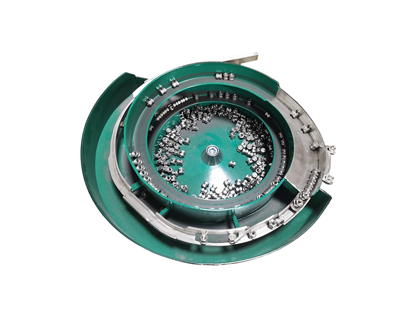
The NexoFeed YH-759 Insert-Molded Nut Vibratory Bowl Feeder provides a catalog reference for evaluating this feeding task. Its final configuration and capacity are determined through sample review. The important selection questions concern insert geometry, orientation and the receiving interface—not a universal speed inferred from the product name.
View the application workflow diagram (conceptual illustration)
Confirm the insert and installation process
Establish whether the component is placed into the mold before injection or installed into a molded part afterward. The feeding requirement may appear similar, but the receiving equipment and production sequence can be quite different. State the actual process in the enquiry and provide the insert drawing rather than referring only to a “brass nut.”
SPIROL distinguishes molded-in inserts, which are positioned before molding, from inserts intended for post-mold installation. Its molded-in range also illustrates that through-hole and blind-ended designs can have different orientation implications. These are useful general distinctions, not specifications for the YH-759 or for your particular insert. Read the manufacturer's explanation.
Separate symmetry from apparent similarity
Review both ends, the outer profile and the internal features. A truly symmetrical insert may not require end-for-end selection, while a blind end, flange or unequal lead-in can make the direction critical. Identify which features the receiving tool uses and which features must face the mold-loading mechanism.
Do not assume that all inserts with the same thread size behave alike. Their external diameters, knurls, shoulders and lengths can differ. A tooling concept developed around one profile must be reviewed before another profile is introduced, even if the purchasing description or nominal thread designation is unchanged.
Describe the final receiving condition
Define where the insert must arrive and how it will be collected. A robot gripper, a transfer shuttle and another loading device can require different support and access arrangements. Specify whether the insert is presented vertically, horizontally or in another approved pose, and identify the feature that establishes that pose.
The final nest should provide a clear interface between feeding and loading. Agree which system confirms availability, which system controls release and what happens after a failed pickup. Without those definitions, the feeder and loading mechanism may each appear to work individually while the combined cell remains unreliable.
Consider surfaces and incoming condition
The external profile may provide useful guiding features, but it can also introduce variations in contact and sliding. Supply inserts in their normal production condition, including approved finishes and permitted residues. Identify surfaces that must remain suitable for the subsequent molding or assembly process.
Inspect the threaded opening and any locating feature before and after trials using the approved criteria. Feeding is not a substitute for incoming quality control. If the application must distinguish mixed sizes or reject a damaged insert, define that inspection task separately rather than assuming orientation tooling will detect every defect.
Review the supply and buffer arrangement
The storage quantity and the working load in the orientation section need not be the same. Discuss how replenishment will occur and how the receiving queue should be regulated. A large available quantity is not useful if the supply behavior overwhelms the part-selection or release arrangement.
For a molding cell, demand can be linked to a repeating loading sequence rather than a continuous stream. Explain how many receiving positions must be served and how the cell handles pauses. The accepted system should respond to that sequence without relying on an operator to correct the queue between cycles.
Define changeover and mixed-part prevention
List the insert variants the application is expected to handle. Compare their external profiles and required presentation, not just their thread specifications. Ask which tooling, nests or recipes are dedicated and which can be shared after validation. Identify how the operator will confirm the installed combination.
Mixed inserts deserve explicit attention because some variants may travel through the same track. Establish incoming identification and line-clearance procedures. If automatic variant verification is required, agree the detection method and challenge conditions. Do not treat successful mechanical travel as proof of correct part identity.
Plan a representative trial
Provide samples covering the normal variation expected in production, with each group labeled. Explain any differences in supplier, finish or drawing revision. Separate deliberate reject samples so the trial team can evaluate them under controlled conditions rather than unintentionally mixing them into normal flow.
The trial should examine the complete feeding route and the proposed pickup condition. Record wrong-end presentation, doubled inserts, missed pickups and visible changes in component condition. Agree how those events affect acceptance. Include normal replenishment and relevant stop-start sequences rather than relying only on a continuous demonstration.
Coordinate the mold-loading boundary
The cell integrator must define the conditions required before the molding machine proceeds. A feeder-ready signal indicates a feeding state; it does not by itself prove that the mold contains the correct inserts in the correct positions. Keep those confirmations distinct in the interface specification.
Discuss recovery after interrupted loading. The procedure should establish the actual state of the mold-loading equipment and presented inserts before restart. Machine safety, access and interlocking must follow the integrator's validated design and the equipment instructions. A general article cannot prescribe a safe sequence for a specific molding machine.
Prepare a quotation package
A clear enquiry allows the engineering team to evaluate the real task:
- Insert drawing, material, finish and production samples.
- Required end orientation and presentation at the pickup point.
- Description of the robot, shuttle or loading device.
- Loading sequence, demand pattern and expected pauses.
- Installation space, access and replenishment arrangement.
- Mixed-part, surface-condition and inspection requirements.
- The proposed responsibility boundary with the cell integrator.
Common questions
Does an insert feeder also install the insert?
Not necessarily. Feeding, transfer and installation are separate functions unless explicitly included in an agreed system scope.
Can a symmetrical insert use simpler orientation tooling?
Possibly, but its actual support and release behavior still need evaluation. Symmetry removes some orientation distinctions; it does not guarantee reliable separation or pickup.
How is the required output established?
Use the loading sequence and agreed pickup condition, then validate the proposed arrangement with samples. Request an insert feeding evaluation using reference YH-759 and include the molding-cell interface information.