GUÍA TÉCNICA
An automated parts feeding system is more than a collection of machines that move components. Its purpose is to deliver the right part in a usable condition when the receiving process can accept it. A project can include capable individual devices and still struggle if the responsibilities between them are not clearly defined.
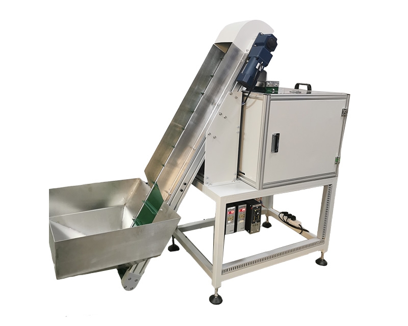
The NexoFeed YH-774 Automated Parts Feeding System is listed as a process-configured system with documented mechanical and electrical interfaces and available sensor and control options. The catalog does not establish one universal configuration or rate. Those details need to be confirmed for the part and the process through application evaluation.
View the application workflow diagram (conceptual illustration)
Draw the actual supply route
Start with the component's arrival condition and follow it to the receiving operation. Identify bulk storage, any orientation stage, intermediate transport and the final presentation. Where the route is not yet decided, describe the required function instead of assigning a machine simply because it appeared in another installation.
Include the people and containers involved in replenishment. An automatic handoff does not eliminate the need for material identification, handling space or a practical refill method. Show the real working environment so the proposed route can be reviewed against access, visibility and existing production activities.
Separate supply demand from machine motion
Describe the quantity and timing of parts required by the receiving process. Specify the component state at delivery and how that state is confirmed. Counting parts moving through an intermediate device is not equivalent to counting acceptable parts available for assembly.
Explain whether demand is steady, intermittent or shared between stations. Include planned pauses and normal operating changes. These conditions allow the supplier to evaluate useful delivery rather than optimize a demonstration that does not represent the production sequence.
Define a boundary for every transfer
For each interface, identify the releasing device, the receiving device and the required part attitude. Record who supplies the supporting structure, final locating feature and mechanical clearance. A drawing should show where one supplier's responsibility ends and the next begins.
Avoid vague descriptions such as “suitable for integration.” Replace them with questions that can be answered: where is the pickup datum, how is a part supported while waiting, and what confirms that the receiving position is clear? The answers should become part of the agreed system definition.
Decide what a buffer must accomplish
A buffer should serve a stated process purpose, such as maintaining supply during a routine replenishment or accommodating a short receiving pause. It is not automatically beneficial to store more components between machines. Waiting parts still require controlled identity, acceptable contact conditions and a known recovery state.
Dorner's accumulation overview illustrates buffering as a distinct material-flow function. It does not establish what arrangement belongs in a NexoFeed proposal. For this project, define the interruption to be accommodated and evaluate a suitable arrangement against the actual components.
Write the control conversation in plain language
Before choosing signal names, describe the intended conversation: the receiver can accept a part, the feeder has a part available, transfer is requested, and the receiving condition is confirmed. The final implementation may differ, but each required state needs an owner and a clear meaning.
Include the response when a confirmation is missing. A timed assumption should not silently replace a required physical check. The controls specification should distinguish normal waiting from a fault and identify which device is responsible for informing the operator that intervention is needed.
Keep inspection requirements explicit
The system may present components without inspecting every feature. If the project needs identity verification, orientation confirmation or a particular quality check, state that separately. Identify the relevant acceptance standard and how rejected or uncertain material will be contained.
Do not infer a verification capability from the presence of a camera or sensor option. Its purpose, limitations and response need to be defined for the application. This avoids discovering during acceptance that different teams assigned different meanings to the same indication.
Design for ordinary production changes
List the expected component variants and explain how often the production mix changes. Review line clearance, tooling identification and the receiving-machine setup together. A quick adjustment on one device may still leave a substantial changeover task elsewhere in the route.
Consider what happens if future variants are introduced. Ask what information would trigger a new evaluation, rather than requesting an unsupported promise that every future component will fit. A documented boundary makes later changes easier to review and reduces accidental use outside the accepted configuration.
Include maintainability in the selection
Ask how the delivered instructions address routine inspection, replacement of wear items and restoration of a known setup. Equipment should be reviewed with the site's maintenance and safety personnel before its final position is fixed. Service access is part of the system layout, not leftover floor space.
Discuss diagnostic evidence as well. An event history that distinguishes supply absence from a receiving pause can be more useful than a single total count. Agree what operators need to observe and what information maintenance personnel need when an interruption cannot be resolved through approved routine actions.
Compare proposals using one requirements sheet
Give each supplier the same description of:
- Part identity, representative samples and incoming condition.
- Required delivery pose and receiving operation.
- Demand sequence and relevant interruptions.
- Buffer purpose and material-control requirements.
- Mechanical and electrical responsibility boundaries.
- Inspection functions and rejected-part handling.
- Changeover scope and acceptance evidence.
Record exclusions alongside inclusions. If a receiving fixture, inspection device or loading activity is supplied by someone else, make that visible. A technically detailed proposal can still be incomplete if a critical boundary is left for the installation team to resolve later.
Frequently asked questions
Is YH-774 one fixed machine layout?
The catalog describes a process-configured architecture. Confirm the proposed arrangement, options and performance for the actual application rather than assuming a standard combination.
Can a larger buffer solve every interruption?
No. It may address a defined supply gap, but it does not correct an uncertain handoff or a receiver that cannot accept parts. Review the cause first.
How should a project begin?
Request a YH-774 system review with a process sketch, part samples and a responsibility list. Use that review to develop a system specification that explains what must happen at every boundary, not merely which devices will be purchased.